INDUCTOR Information
We are pleased to provide detailed information
on TNC Co., Ltd.’s EMI technology capabilities and solutions.
·What is Coil
A simple structure in which wire is wound around a magnetic core (CORE), with its performance and characteristics determined by the core material.
·The principle by which a coil has impedance.
- Maximum flux density (Bm): A coil functions as an inductor as magnetic flux changes. As current increases, the magnetic flux also increases, but it cannot exceed the maximum flux density Bm. This state is called magnetic saturation. Once magnetic saturation occurs, no further flux change happens, and the coil behaves like a simple wire. Generally, Bm has temperature-dependent characteristics.
- Permeability (μ): It depends on the current, and the inductance of a coil varies with the current. A higher μ results in greater inductance. It also has temperature characteristics—μ increases with rising temperature but drops sharply beyond the Curie point.
·Small Signal Coil
Used in high-frequency filters or small-signal chokes; performance deteriorates if saturation current is exceeded.
·Noise Suppression Coil (for CM/DM)
Forms a low-pass filter with capacitors to eliminate high-frequency noise components.
·Power Factor Correction Coil
Controls large currents at the operating frequency to improve power factor; characterized by a large and heavy form.
·Smoothing Coil
Used for smoothing on the secondary side of an SMPS; caution needed due to magnetic saturation from high current.
·Pre-saturated Inductor
Employs core material with a sharply rising B-H curve; used in mag-amp type SMPS.
| MODE | Material Name | Initial Permeability | Applicable Frequency | COST |
|---|---|---|---|---|
| DM | Iron Power | 5 ~ 82 | ~ 100MHZ | Low-cost ↓ High-cost |
| Kool MU | 60 ~ 125 | ~ 1MHZ | ||
| Sendust | 26 ~ 125 | ~ 2MHZ | ||
| High Flux | 14 ~ 160 | ~ 1MHZ | ||
| MPP | 14 ~ 550 | ~ 1MHZ | ||
| Amorphous (Iron-base) | 5,000 ~ 10,000 | ~ 0.5MHZ | ||
| CM | Ferrite(Mn-Zn) | 750 ~ 15,000 | ~ 2MHZ | Low-cost ↓ High-cost |
| Ferrite(Ni-Zn) | 10 ~ 1,500 | ~ 100MHZ | ||
| Amorphous (Cobatt-base) | 60,000 ~ 100,000 | ~ 0.5MHZ | ||
| Finement | 30,000 ~ 50,000 | ~ 0.5MHZ |
·Permeability, Inductance, DC0BIAS↓ : Applied to COMMON
·Permeability : High-frequency
·Permeability : Low-frequency
·Coil frequency is determined by the impedance of the magnetic material
The winding method of a coil is crucial in determining the inductor’s characteristics, current capacity, and operating frequency. The winding methods include:
- Loosely wound single-layer winding
- Densely wound single-layer winding
- Multi-layer winding
- Sectional winding
- Twisted pair winding
·Permeability
The most important term that defines the characteristics of magnetic materials, which varies depending on the material properties, magnetic field strength, frequency, and temperature, and is typically unitless. It is generally defined as the ratio of the magnetic flux density induced in the material to the magnetizing force (magnetic field strength) that produces it.
·Magnetic Flux(B : Wb, ψ)
The shape of the magnetic force acting from the north (N) pole to the south (S) pole is called a magnetic field line, and the collection of these field lines is referred to as magnetic flux.
·Magnetic Flux Density(Gauss, : Wb/㎡)
It refers to the total number of magnetic field lines passing perpendicularly through a unit area. When a current i flows through a conductor l placed in a magnetic field, the force F acting on the conductor is given by:
F (N) = i (A) × B × l (m) Solving for B, the magnetic flux density: B = F / (i × l) [Unit: Tesla (T) or Wb/㎡]
·Magnetic Field Strength(H : AT/m, Oe)
The region where magnetic field lines exist is called a magnetic field (or magnetic field space), as magnetic force acts within it. When a unit magnetic pole is placed at a point within this field, the strength of the magnetic force acting on it defines the magnetic field strength at that point.
·Saturation Flux Density(Bs : m/T)
This is the point at which an increase in magnetic field strength no longer results in an increase in magnetic flux density—the material becomes magnetically saturated. A higher Bs means the core can handle stronger magnetic fields, allowing it to control higher voltages without saturating.
·Curie Temperature(Tc : ℃)
This is the critical temperature at which a core material transitions from ferromagnetic to paramagnetic behavior. It is defined as the temperature where the permeability (μ) drops to 1, determined by drawing a straight line between the points where μ reaches 80% and 20% of its maximum value (μmax). This temperature is a key factor in selecting core materials.
·Q
When current flows through a coil after inductor fabrication, ideally ½·U² of energy should be stored. However, losses in the core and winding reduce this storage capability. Since the winding resistance is primarily low DC resistance, the Q factor is initially high. But as frequency increases, skin effect and winding capacitance cause the Q factor to decrease.
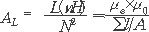
·Inductance Factor 
It is a standardized term used frequently in coil winding to provide predicted inductance information based on the core shape, such as toroidal, E, U, or pot cores. This value is typically given by the manufacturer as , often provided in data sheets. It represents the inductance per turn squared and helps designers estimate the inductance without physically winding the core first.